I am not a computer scientist. Nor have I really had any CS courses. Far from it. I hold two degrees in literature and literary theory. So, when I started to wonder how computers work (since I use them every day!) I had to go about teaching myself. While I have some experience with contemporary programming languages, I also wanted to start with the building blocks of the computer age:
Logic gates.
The beginnings of computing and logic gates starts with telephone companies in the early-mid 20th century, and telephone companies did this with relays.
So that is where I needed to start: create relay logic gates of my design.
DPDT Relays

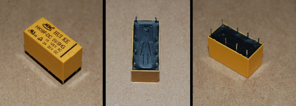
The first thing I did was order some relays. Well, really the first thing I did was learn what relays are, what kinds there are, and what it is exactly that they do. Then I went bargain hunting. On Amazon I found some cheap 5 volt relays. I wanted 5v because it was a voltage that I understood (USB runs off it, 4 AA batteries produce it). These cheap relays were DPDT (double pole double throw) so I started drawing up some custom schematics for making some basic logic gates.
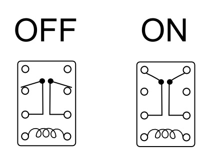
Firstly, I had to understand how a DPDT relay looks in its OFF state and its ON state in order to understand how to develop logic gates.

Relays work by having a mechanical switch that is triggered magnetically when a coil is electrified. For my particular relays, putting 5V through the coil throws two switches from on OFF pole to an ON pole. In the diagram above I repsesented the “hinge” of the switch as a little black dot. Hopefully you can see how this works. Essentially, in data terms, this gives you two binary bits controlled by a single input. Both bits are zero (OFF) until the coil is powered, making them both 1 (ON). Off course you don’t have to use both bits on a DPDT when building logic gates, but it can be useful. A single pole double throw relay (SPDT) works the same way except it only controls a single bit. A SPDT would work fine for building logic, it would just take more of them, and oddly enough DPDT switches seemed cheaper and easier to find.
With the relay as the basic building block, I set about designing my own logic gates. The two basic logic gates are the AND gate and the OR gate. I pulled this chart from the Wikipedia page on Logic Gates:
| Type | Boolean | Truth Table | ||||||||||||||||||
| AND | A & B |
|
||||||||||||||||||
| OR | A or B |
|
||||||||||||||||||
Relay AND Gate
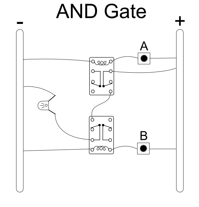
Truth tables are an important part of understanding basic computer logic, and they give me the clearest picture of what’s happening. For example, look at the AND gate truth table above. Only when input A and input B are 1 (meaning that they have a current flowing through them) does the output result in 1 (meaning that the electricity flows out of the gate.) Using the truth table as a guide I desgined the following logic gate using my DPDT relays.

The schematic setup looks a little like a breadboard because that is the easiest way for me to wrap my head around the design. The right rail is positively charged while the left rail is connected to ground, giving it a negative charge. A and B inputs here are represented by push-button switches that only allow a current through when pressed. This just helped me to imagine turning A and B off and on as I was designing the circuit.
The object to the left of the relays is an LED so that I could conceptualize some kind of output. If this were to be made into a real circuit the LED (depending on its type) would likely need a resistor behind it so that it doesn’t burn out at straight 5V.
While designing the circuits I tried to imagine following the flow of current down the lines from the positive rail as it passed through the buttons, relays, and LED all the way to the ground rail. If the coil is activated as power passes through it then I conceptualized the relay switches being thrown and then tried to see if power could then flow through the relay in its on state.
Of course with the AND gate, the objective is to create a circuit where the LED is only supplied with power when both A & B input buttons are pressed. The above schematic fulfills this objective. No doubt there is a simpler way to do this, but I must remind you: I am am not a trained computer scientist. That being said, what I did works for me.
Relay OR Gate
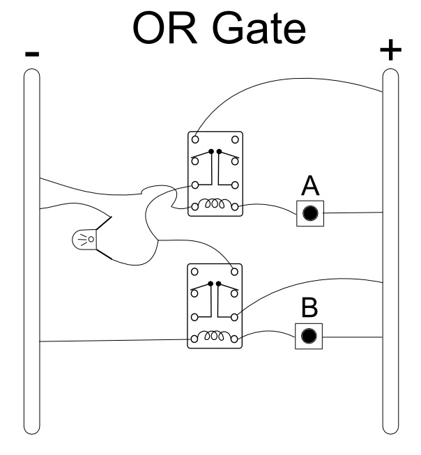
Making an OR gate can be relatively simple. Some people would argue for simply wiring the output of the two buttons together directly to the LED. However, this can lead to the current flowing backwards through your circuit and can cause problems as you develop more sophisticated logic from these building blocks. So I made a simple OR gate using two DPDT relays:

Looking at the Truth table above and the OR gate circuit, hopefully you can see how this results in a working OR gate.
With these basic logic gates sorted out, I could now think about doing something a little more advanced. Using these basic logic gates (and one more type) I designed my own Half Adder and Full Adder circuits using relays.